DYNAMIC ANALYSIS OF FLEXIBLE CONNECTION STRUCTURE FOR NEW TYPE LIGHT STRUCTURE
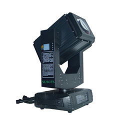
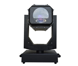
Large span lifting stage structure shown in Figure 1, the components for the independent manufacturing, through the connection structure for assembly. As the equipment volume, production and location accuracy is difficult to control in the design requirements within the scope of the installation need to compensate for certain errors, to achieve floating adjustment. At the same time, during the operation of the equipment, the state of motion is often changed, such as acceleration, rise, fall, emergency braking. Sudden changes in the operating state will lead to structural impact load, affecting the smooth operation of equipment.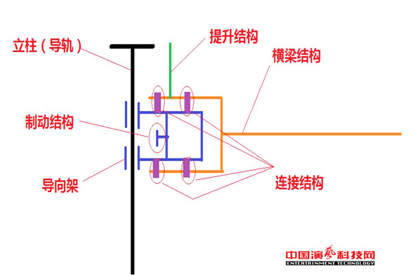
Figure 1 Schematic diagram of the lifting stage structure
The new flexible connection structure shown in Figure 2, the beam end of the design of a concave structure, set in the convex frame outside the structure. A vertical through hole is provided in the vertical direction of the connection between the beam and the guide frame for mounting the limit shaft. Between the two for the gap with a certain amount of space margin. The adjustment assembly mounting hole is arranged around the end of the beam, and the elastic structure is placed on the guide frame through the preload pressure to form a reliable flexible connection. The new connection structure has certain elastic space in X, Y and Z directions, which can meet the requirement of floating position adjustment when the equipment is installed.
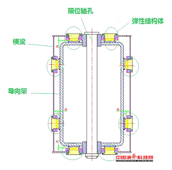
Figure 2 new flexible connection structure
1 to enhance the transient dynamics of the stage structure
Transient dynamics are a method used to determine the structural dynamics of a load subjected to time variation. In this paper, a simplified model is used to simulate the sudden emergency braking in the process of accelerating the rise. The model is analyzed and compared with the traditional rigid connection and the new type of flexible connection. The model is shown in Fig. As the structure and load symmetry, the establishment of half of the model for analysis. Assuming that the structure is raised at a speed of 3 280 mm / s2, a braking force of 352.8 kN is applied at the guide frame brake position 3. The use of rod, beam, shell unit hybrid modeling, ignoring the stage structure, the use of quality unit simulation. Rigid connection using beam element simulation, flexible structure using a circle of spring unit simulation. All the degrees of freedom at the bottom of the column are constrained, and the three translational degrees of freedom at the bottom of the pull plate are raised, and the symmetry constraint along the plane Y and Z directions is applied to the model symmetry plane position.
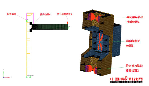
Figure 3 Structural model and key location description
2 Analysis results
Through the modal calculation, the first order natural frequency f1 = 1.98 Hz. According to experience, the structural damping is 0.2 and the equivalent viscous damping conversion coefficient is W = 2πf = 12.43. The time step D = 0.01 <1 / (20 × f) = 0.025 is calculated using the direct transient method.
2.1 Comparison of key position forces
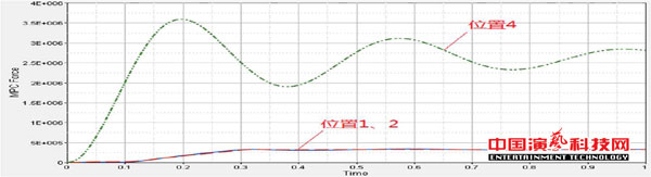
The curves of the load of the two structures at the positions 1, 2 and 4 are shown as the curves of the force of the guide frame on the upper and lower contact positions of the guide rail under the impact load, and the change of the position force. The As can be seen from Fig. 4 and Fig. 5, the two connection structures have no significant effect on the lifting load, i.e., position 4. With a rigid connection, the force of position 1 is greater than the force of position 2. This is due to the bending moment transmitted from the beam, and the two positions of the force with time changes have a certain fluctuation, due to the existence of structural damping, fluctuations gradually flat. With the flexible connection, the force at position 1 is consistent, and due to the role of elastic damping, the load changes smoothly, there is no oscillation phenomenon.
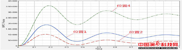
Figure 4 Rigid connection key position load curve
2.2 Comparison of key position displacement values
The curves of the displacement of the two structures with displacement and flexibility at position 1 and 2 show the displacement curve of the guide rail on the upper and lower contact positions of the guide rail under the impact load. It can be seen from Fig. 6 and Fig. 7 that the displacement at the position 1,2 is greater than that of the rigid connection structure with a peak value of 8 mm and the deformation amount is smaller and does not exceed the elastic space of the flexible connection structure.
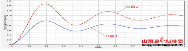
Figure 6 Rigid connection key position displacement curve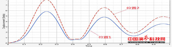 Figure 7 Flexible connection key position displacement curve
2.3 Comparison of structural stress results
In the 1 s time step, the use of rigid connection, the maximum stress on the surface of the rigid frame on the rigid connection position, the stress value of 334.8 MPa. With the flexible connection, the maximum stress is located in the lower surface of the guide frame elastomer support position, the stress value is 261.1 MPa. In contrast, the use of flexible connection guide structure stress value is small. The simulation results are shown in Fig. 8 and Fig. In the 1 s time step, the use of rigid connection, column structure section stress maximum 56.4 MPa. With the flexible connection, the maximum stress of the section is 55.73 MPa. In contrast to the guide rail structure with the guide frame contact position, the use of flexible connection, rail stress value is less than the use of rigid connection structure. The simulation results are shown in Fig. 10 and Fig.
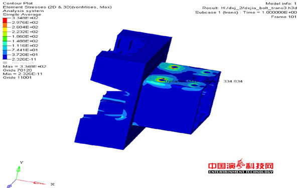
图8 刚性连接导向架结构应力云图
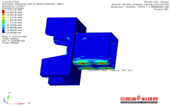
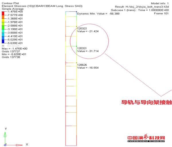 Figure 10 Rigid connection column structure axial stress cloud
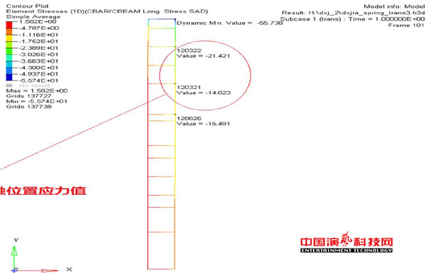 Figure 11 Flexible connection column structure axial stress cloudExcerpt from "Performing Arts" 2015 the twelfth