Application of Mechanical Lifting in Flexible Driven Column
1 Overview
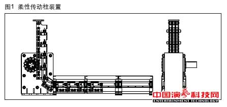
Flexible drive column device is based on the roller chain drive, combined with a square hollow column with high overall stability and other characteristics developed, and the current flexible teeth, rigid chain has the same function, but its carrying capacity and travel are very Big improvement, see Figure 1.
Flexible drive column device with the following main features:
(1) the horizontal movement of the chain through the roller chain transmission box into a vertical movement, to achieve vertical lift.
(2) to change the soft roller chain into a rigid link with one-way stiffness, rigid link between the articulated hinge to form a vertical column (rigid) to withstand the vertical load.
(3) The double-axis of the single-row standard roller link and the parallel multi-section roller link simultaneously convey the movement and load (similar to the multi-row roller chain, but with the standard roller chain connection between different ways) The stiffness of the link, the carrying capacity and the overall stability of the column structure frame.
(4) repeat positioning high precision, smooth operation, high reliability, long life, low maintenance, flexible configuration, easy installation, to adapt to heavy loads (single flexible drive device maximum load of up to 60 t) and shallow foundation pit Stroke, single flexible drive column device maximum travel up to 18 m or more.
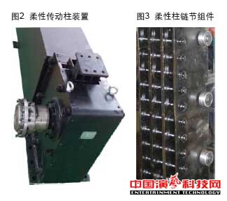
Flexible drive column device is mainly for the shallow foundation pit drive to provide a large range of solutions can be used for specific production line lifting parts, but also for scissors, screw, hydraulic cylinder, flexible teeth, large spiral, Li n kLi ft series And other areas, in particular, to meet the mechanized stage of the shallow foundation pit, the use of large load requirements, but also for some new areas to provide high quality and reliable transmission. Figure 2 for the flexible column gear box, Figure 3 for the flexible column link module.
2 design mechanism
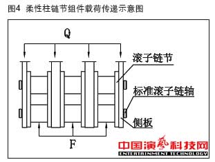
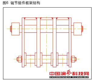
Figure 4 for the flexible column link component load transfer diagram. It can be seen in the figure, under the action of the load Q, through the four side panels of the two standard roller chain shaft to the load to the three-way roller links, three sections of the chain link to the drive sprocket F The In the heat treatment, the roller chain plate and the standard roller chain shaft and the hardness of the side plate is inconsistent, the purpose is that the side plate under the action of the load Q micro-deformation occurs, so that the two-axis bearing at the same time, increase the axis of the shear surface (6 To 12) and the side plate of the compression surface (4 to 8), improve the carrying capacity, increase safety. Figure 5 for the flexible column link assembly and sprocket meshing diagram. The three plates are welded together with the rear of the four side panels, and the roller chains at the front of the four side panels are connected together with the pins to form a stable cross section of three cavity structures to improve overall stability. Is other similar structure does not have the characteristics, as shown in Figure 6.

Brief introduction of several typical one - way rigid transmission structures
(1) the French rigid link Linklift can be seen as two parallel plates by the vertical parallel plate connected to the formation of the connecting shaft column, and then the column will be cut into a section of the chain, adjacent two by another pair of chains The hinges are hinged together to form a one-way rigid drive.
(2) the flexible teeth can be regarded as a column formed by a rack, and then the column rack cut into sections of a section of the teeth, adjacent two sections by the other plate hinge or directly hinged together to form a single To the rigid drive.
(3) flexible drive column device with a good consistency of the square stiffness of the square tube as a design concept, a square tube as a drive column, the drive column to install the national standard roller chain, and then cut into a column Section section to form a link component, adjacent two sections by special connection hinge, the formation of one-way rigid transmission. Due to the difference between the driving mode and the mechanism of force, the lateral stiffness and load characteristics are different. According to the characteristics of the standard roller chain, the stiffness and the load of the flexible column can be combined with the characteristics of the double-axis bearing at the standard link Bigger, stronger, easy to form a standard series.
4 flexible drive column device
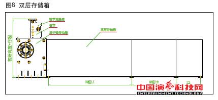
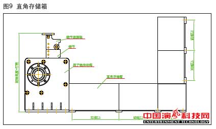
The chain of the roller chain consists of a chain connecting seat, a number of knuckles, a roller chain transmission box and a chain storage box. The roller chain storage box has a single layer (see Fig. 7), a double layer (see Fig. 8) and a right angle (See Figure 9) in three forms.
程上的载5 technical parameters
Flexible drive column device performance parameters are as follows:
Speed: maximum speed 0.25 m / s drive efficiency: 0.80-0.90 installation vertical requirements: 1 mm / m, 3 mm / full stroke allows maximum static load: static load = 1.3 ~ 1.4 × dynamic load dynamic load factor: 1.1 ~ 1.2 (Speed <0.25 m / s) Noise conditions: 50 dB at the speed of 0.1 m / s Repeatability: <3 mm Flexible drive column drive geometry as shown in Table 1, load stroke and stroke (With guide system) As shown in Table 2, 12 A -48 A dynamic load and stroke curve (with guidance system) as shown in Figure 10. Table 2 shows the load for the chooseion reference if the guidance system is safe and reliable on the same line
The Dutch may be appropriately increased, but the maximum carrying capacity will be the same.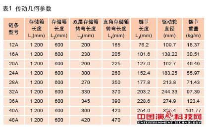 Table 2 Dynamic load and stroke (with guidance system)
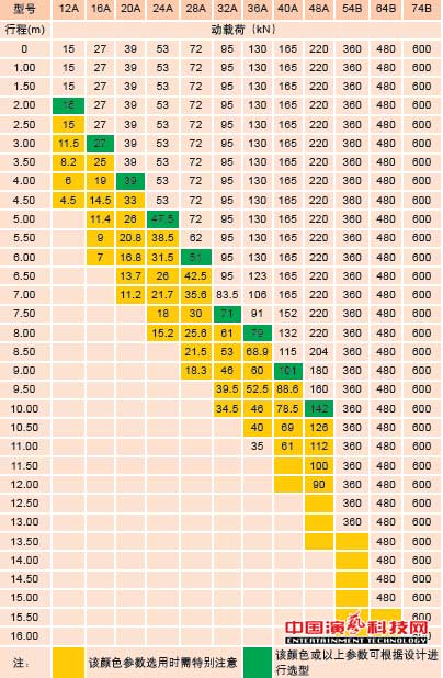
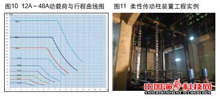 6 Application Case 6.1 Engineering Example Flexible drive column device was officially launched in April 2011, by several well-known domestic stage integrators of concern, has been successfully applied to its projects, and by the relevant industry-related companies concerned. Figure 11 for a radio and television center installation of the trip 7.4 m, model 28A flexible column. 6.2 Case 1 Technical parameters: Table size: 18 m × 3 m, the effective area of 54 square meters depth of the pit(m):1.1 working stroke (m): 1.4 dynamic load (kN / ㎡): 1.00 static load (kN / ㎡): 5.00 speed (m / min): 3 guide system: two-stage guide column or scissors device layout: 6.3 Case 2 Design parameters: Table size: 18 m × 3 m, effective area: 54 ㎡ Foundation pit depth (m): 13.3 Working stroke (m): ± 4Dynamic load (kN / ㎡): 4.0 Static load (kN / ㎡): 7.5 Speed (m / min): 12 Guide system: 4 tracks
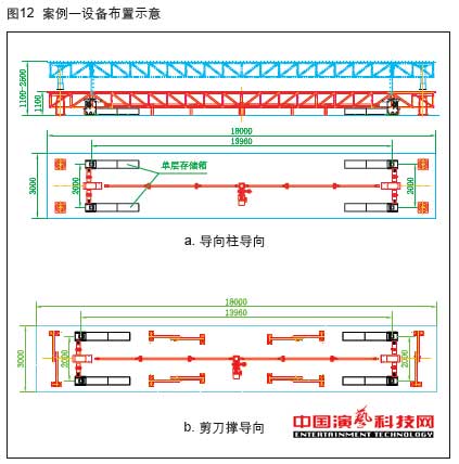 备布置:见图13
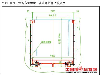
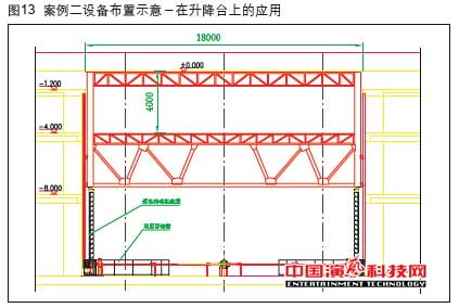 6.(M): 1.40 working stroke (m): 7 motion, static load (kN / ㎡): 4.00 speed (m): 3 m, / min): 9 Guide system: 4 rail equipment layout: see Figure 14