The method of detecting professional speaker performance
(See Table 1), output characteristics (see Table 2), frequency characteristics (see Table 3), point to the characteristics (see Table 4), impedance and its derived characteristics (see Table 5), the main features of the professional speaker, And amplitude non-linearity (see Table 6). These characteristics are described in detail below.
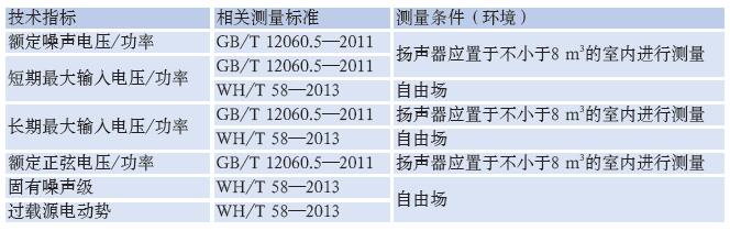
表1 输入特性
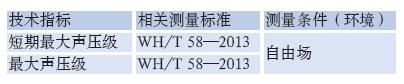
表2 输出特性
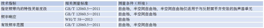
表3 频率特性
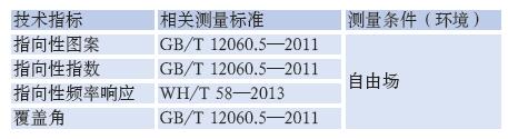
表4 指向特性
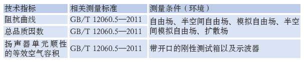
表5 阻抗及其派生特性
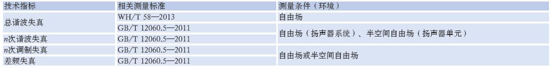
Table 6 Amplitude nonlinearity
1 input characteristics
1.1 Rated noise voltage
GB / T 12060.5-2011 specifies that the analog noise of the loudspeaker in the event of no thermal damage or mechanical damage is called the rated noise voltage. When measuring the rated noise voltage, the loudspeaker should be measured in a room of not less than 8 m3.
1.2 short-term maximum input voltage and long-term maximum input voltage
Considering the use of the loudspeaker in the extreme case, GB / T 12060.5-2011 and WH / T58-2013 all specify the analog program signal that the speaker unit or system can withstand for 1 s without permanent damage Of the maximum voltage for the short-term maximum voltage, can withstand the time of 1 min analog program signal maximum voltage for the long-term maximum voltage. It is noteworthy that GB / T 12060.5-2011 provides a measurement environment is not less than 8 m3 of the room, and WH / T58-2013 is required in the free field.
1.3 Rated sinusoidal voltage
GB / T 12060.5-2011 stipulates that the rated sinusoidal voltage is within the rated frequency range so that the speaker can continue to work without causing any thermal damage or mechanical damage to the continuous sinusoidal signal voltage. When measuring the rated sinusoidal voltage, the loudspeaker should be measured in a room of not less than 8 m3.
1.4 inherent noise level
WH / T 58-2013 stipulates that in the rated working conditions, remove all the signal source, and all the input shorted, the volume potentiometer placed in the maximum, the tone control should be placed in the vertical position of the pitch control The The A-rated sound pressure level measured at 1 m from the reference point on the reference axis of the speaker system is the inherent noise level. The measurement of the inherent noise level should be carried out in the free field.
1.5 overload source electromotive force
WH / T 58-2013 stipulates that the measurement of the overload source electromotive force should be in the speaker system under rated operating conditions, and in the free field.
2 output characteristics
2.1 short-term maximum sound pressure level
WH / T 58-2013, in the rated working conditions, the signal with a burst signal, the active speaker system, the volume potentiometer placed in the maximum position, adjust the noise signal source output signal size. Enter the voltage of the minimum source electromotive force of 1/8 times to start testing the frequency response curve and record it. The input signal is incremented by 3 dB each time, when the input signal is incremented by 3 dB and the sound pressure level no longer rises by 3 dB and only 50% of the input increment is reached, the output sound pressure level is short Sound pressure level. Measuring the shortest maximum sound pressure level should be carried out in the free field.
2.2 Maximum sound pressure level
WH / T 58-2013 stipulates that under the rated operating conditions, the first input voltage of 1/8 times the minimum source electromotive force begins to test the frequency response curve and record. In this case, the total harmonic distortion in the specified frequency range is tested and the sound pressure level of the total harmonic distortion curve is compared with the sound pressure level of the frequency response curve until the distortion reaches the specified requirement. The sound pressure level at each frequency point in the response curve is the maximum sound pressure level. The maximum measured sound pressure level should be carried out in the free field.
3 frequency characteristics
3.1 Characteristic sensitivity level in the specified frequency band
GB / T 12060.5-2011 stipulates that when measuring the sensitivity level within a specified frequency band, the loudspeaker should be placed in a free or half free space environment and measured under normal measurement conditions. The half-space free field is only suitable for loudspeaker units that are flush with the reflector.
3.2 Frequency response
GB / T 12060.5-2011 provides that the measurement of frequency response should be in the free field or half space free field conditions. WH / T 58-2013 stipulates that measuring the frequency response of an active loudspeaker system should be carried out under free field conditions.
3.3 Effective frequency range
GB / T 12060.5-2011 provides that the effective frequency range is defined by the upper and lower limits of the frequency range. The upper and lower frequencies of 10 dB below the average sound pressure level within the bandwidth of an octave band in the highest sensitivity region, on the speaker frequency response measured on the reference axis. The measured effective frequency range shall be carried out in free or half free space conditions.
4 Pointing characteristics
4.1 directional pattern
GB / T 12060.5-2011 provides that the measurement directivity pattern should be carried out under free field conditions. AES 56-2008 specifies the measurement method for the directional characteristics of the loudspeaker system. Contains the measurement conditions, the spatial resolution of the measuring points, and the test data. The test reference distance is 10 m, which is required in a relatively stable acoustic environment, and the repeatability of the measurement is ensured by detecting the repeated test data. The spatial distribution of the points can be divided into the A-type distribution that generally describes the speakers pointing characteristics and the B-type distribution for the fully symmetric or semi-symmetrical loudspeaker. (15 ° × 15 °), medium resolution distribution (15 ° × 5 °), and general resolution (15 ° × 5 °), with a resolution of 5 ° × 5 ° and a total space of 2 664. Resolution distribution (5 ° × 5 °), are half-space measurements.
4.2 Directivity index
GB / T 12060.5-2011 provides that the measurement directivity index should be carried out under free field conditions.
4.3 Directional frequency response
WH / T 58-2013 stipulates that the measurement of the directional frequency response should be carried out in the free field.
4.4 cover angle
GB / T 12060.5-2011 provides that the coverage angle should be measured in the free field conditions. And for a loudspeaker designed to have a different coverage angle on different planes of the reference axis, the coverage angle should be measured in at least two mutually perpendicular planes.
5 impedance and its derived characteristics
5.1 Impedance curve
GB / T 12060.5-2011 provides that the impedance curve of the measurement conditions for the free field, half space free field, simulated free field, half space simulation free field, diffusion field.
5.2 Total Quality Factor Qt
GB / T 12060.5-2011 provides that the total quality factor Qt measurement conditions for the free field, half space free field, simulated free field, half space simulation free field, diffusion field.
5.3 Equivalent air volume for speaker unit compliance
GB / T 12060.5-2011 provides that the equivalent air volume of the speaker unit is measured with a rigid test box with an opening and an oscilloscope.
6 amplitude nonlinearity
WH / T 58-2013 specifies that the total harmonic distortion of the active loudspeaker system should be carried out under free field conditions. GB / T 12060.5-2011 stipulates that when measuring total harmonic distortion, nth harmonic distortion, n modulation distortion and difference frequency distortion, the speaker system should be placed under free field conditions, the speaker unit should be placed in a half space free field Under conditions.